The Entity Relationship Model.
Introduction to the scenario.
The scenario is about the academic institute. An academic institute in your town wants to set up a database to record details about its staff, and the departments they belong to. They intend to record the following information. For each member of staff, their staff identity number, name, job title, and salary, for each department, its name and address, and for each member of staff, all departments that they belong to. It is required that every member of staff belongs to at least one department. For each department, there is a head of department. It is required that each department has exactly one head of department. Develop a system to manage the day-to-day business of this institute.
Message from the group students.
We are group 04 from EEI-3266-WD-E-G11. We are five members in our group. They are, M.Diresh (s92060986), AM.Aroos (s92065965), V.Jemika (s92085752), MM.Zahra (s92085832),S.Sarmijan (s92082608), Y.Yohendran(s92082619).

What is ER Diagram?
ER Diagram stands for Entity Relationship Diagram, also known as ER Diagram is a diagram that displays the relationship of entity sets stored in a database. In other words, ER diagrams help to explain the logical structure of databases. ER diagrams are created based on three basic concepts: entities, attributes and relationships.
ER Diagrams contain different symbols that use rectangles to represent entities, ovals to define attributes and diamond shapes to represent relationships.
At first look, an ER diagram looks very similar to the flowchart. However, ER Diagram includes many specialized symbols, and its meanings make this model unique. The purpose of ER Diagram is to represent the entity framework infrastructure.
Identification of Entities.
WHAT IS ENTITY?
A real-world thing either living or non-living that is easily recognizable and non-recognizable. It is anything in the enterprise that is to be represented in our database. It may be a physical thing or simply a fact about the enterprise or an event that happens in the real world.
An entity can be place, person, object, event or a concept, which stores data in the database. The characteristics of entities are must have an attribute, and a unique key. Every entity is made up of some ‘attributes’ which represent that entity.
Examples of entities:
- Person: Employee, Student, Patient
- Place: Store, Building
- Object: Machine, product, and Car
- Event: Sale, Registration, Renewal
- Concept: Account, Course
Identification of Attributes
It is a single-valued property of either an entity-type or a relationship-type.For example, a lecture might have attributes: time, date, duration, place, etc.In this scenario,there are three Entities, for those entities having some attributes. An attribute in ER Diagram as follows.
.jpg)
Identification of Relationships.
There are three types of relationships between entities (tables) in data modeling
1.One-to-many relationships (also denoted as 1:M).
2.Many-to-many relationships (M:N).
3.One-to-one relationships (1:1).
The most common type of relationship is a ONE-TO-MANY RELATIONSHIP, where a record in one entity can be referenced by multiple records in another entity. Another common type is a MANY-TO-MANY RELATIONSHIP.
This type of relationship is only used in logical data models. In a physical database, it has to be implemented by USING ONE-TO-MANY RELATIONSHIPS and a junction table.
In this article, we’ll discuss the third type of relationships: the one-to-one relationship. This is the least common type of relationship in a data model. We’ll give examples of one-to-one relationships, show the notation for one-to-one relationships in an ER diagram, and discuss one-to-one relationships in practice.
This is the ER Diagram of the following scenario.

ER Diagram with assumptions and explanation.
1.The department allows the staffs to add their information in to the database.
2.Each staff is identified by Staff_ID
3. A single staff can communicate with one or more Departments
4.Staff _Id is concern as a foreign key in the department unit.
5.Every staff can communicate the departments but department only can communicate the head of departments.
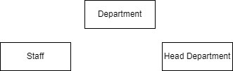
Identification of Actors.
There are three ACTORS in this scenario.
1.STAFF :a group of persons, as employees, charged with carrying out the work of an establishment or executing some undertaking.
2. DEPARTMENT : a distinct part of anything arranged in divisions; a division of a complex whole or organized system.
3. HEAD DEPARTMENT : This department functions as the head department of many departments.
Identification of Business Processes.
The center has 3 divisions namely Staffs, Department and Head Department.Every worker who works here can work in more than one of the departments here.
All workers can work in all departments. As well as a head department in for all departments.
Functional Requirements of the system.
Student shall give test
o Student shall communicate the teacher
o Teacher shall login
o Teacher shall communicate with admin,student and parents
o Teacher shall assign assignments to the student
o Teacher shall collect assignment of his student.
o Teacher shall take test online
o Teacher shall mark attendance online
o Parents shall login through his child Id
Non-Functional Requirements of the system
NON FUNCTIONAL REQUIREMENTS :
o Security :- only authorized users can access the staff user name and password
o Performance:- Easy tracking of records and updation can be done
o user friendly :- The system is very interactive
o Maintionability :- Backups for database are available
o The system should be available 24 hours
o The system should be response at the time
Normalization of the Relation drawn using the ER Diagram.
This table depicts all the information of this Database.

This Tables are showing a department and Staff only Informations
- Staff

- Department

This is a Normalized table.

Relational Database schema with foreign key references.
This is the relational database Schema of the following scenario
Staff ( id_number, name, job title, salary )
Department (name, address )
Head_department
Screenshots of MySQL workbench (SQL commands and the result set).
This is a SQL workbench Screenshot which is created as a group by our group members.

Few SELECT, UPDATE and DELETE queries executed on the tables explaining the result giving screen shots of the SQL queries and the result set.
create database academicInstitute;
use academicInstitute;
create table staff(
identy_no int primary key,
Sta_name varchar(12),
job_title varchar(20),
salary int
);
create table department(
de_name varchar(12),
address varchar(30)
);
insert into staff(identy_no, Sta_name, job_title, salary)
values(123456789, "Kamal", "Manager", 20000),
(123456790, "Aamal", "AssistantManager", 15000);
insert into department(de_name, address)
values( "KAI", "13,Main street,Batticaloa"),
("MDA", "20,Main street,Eravur");
/Select/
select Sta_name, job_title, salary from staff where identy_no="123456789";
/update/
update staff set salary=18000 where salary=15000;
/delete/
delete from department where de_name="MDA";
Comments
Post a Comment